Image Processing
Performed tests were done using various basic image processing
tools. We used Khoral Research's Khoros ©(TM), John Bradley's
xv ©, Adobe Photoshop ©(TM) and a couple of programs
that we wrote ourselves in C and Visual Basic(TM). In this chapter
are presented results from various basic image processing methods
applied to an image produced by a flat scanner.
The tested methods include histogram modification,
thresholding, edge-detection algorithms, median filtering,
averaging, combinations of these, and a few of our own methods,
the deviation and papyrus structure elimination methods.
Because these methods are supposed to be used as
tools for humans, and controllable by them, most of them
have interactively adjusted variables. Algorithms
for automatic detection of certain values, as thresholds,
are presented where applicable.
Image Analysis
Histograms
The original sample is presented in figure [27].
Histogram of it, in [figure 28], shows that in this
case the grey levels produce quite a continuous curve,
except for a periodic pattern (the periodic behaviour can
be seen in many of the histograms of scanned images,
and is due to slight stretching of the grey scale
by the scanner or the controlling software).
The characters don't seem to stand out as a separate peak, indicating
potential difficulties in simply thresholding the image.
The background, shown in the North-East corner and in the three holes
of figure [27], cause the peak at greyscale values over 250.
Comparing two histograms figure [29],
one from inside the characters (generated from six approximately
10x10 pixel areas inside different characters) and the other from
background (six 20x20 pixel areas), one can observe the grey
level distributions.
The grey levels are more randomly scattered in the background,
and the pixel values of a character seem to stay within a certain range,
in this case, approximately within the interval from 50 to 80
intensity units (grey level values).
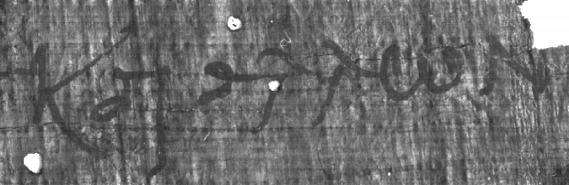
Figure 27:
The sample image, scanned directly from the object with a flat
scanner [640x208].
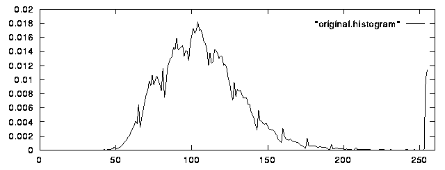 Figure 28:
Histogram of the original sample image.
Figure 28:
Histogram of the original sample image.
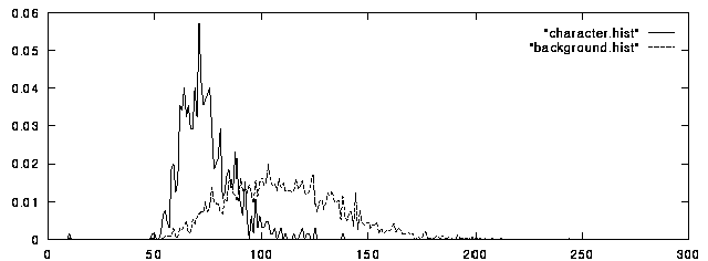
Figure 29:
Histograms of character (left) and background (right).
Profiles
A profile, the grey values along a line, is shown
in [figure 30]. The line was taken horizontally, at the level
of the small, white hole near the center of the image (in the
first 'lambda' character), which
causes the highest peak in the figure. The characters, but also
the dark background areas, form the "wells" of the profile.
The overall impression is that the profile is quite noisy,
and that the characters cannot be easily identified from it.
A closer look of the edges of the characters is presented
as an example in [figure 31]. It is a 42 pixels wide profile
of a single vertical
stroke from the lower left part of 'K'. The pixels no:s
13-30 belong to the character. The left edge is not very clear,
because the background is almost equally dark so that there's no
sudden change in grey level values.
The right edge is quite identifiable. The grey level values
increase rapidly and stay at the higher level.
This profile was captured from maximum resolution sample
picture (1386x451).
If the grey level values of a character change rapidly near the
edges, the edge might be identifiable by edge-detection algorithms.
In an ideal black-and-white image the insides of characters
would be flat zero and the profile of the edge would be vertical.
In our case we have much noise (randomness of the background),
and parts of the background look much like some parts of some
characters. The recording has also smoothed the edeges slightly.
Figure 27:
The sample image.
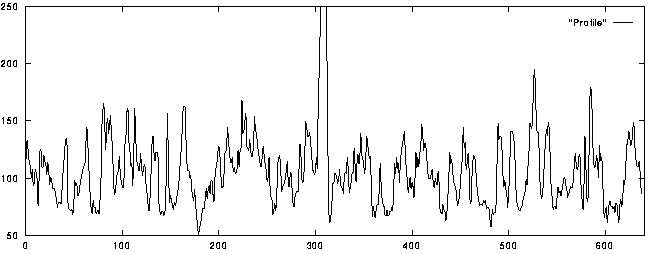
Figure 30:
Horizontal profile of test image. The peak at 300 is caused by
the small hole in the first 'lambda'.
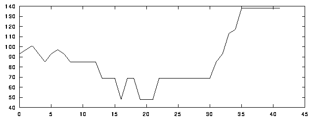 Figure 31:
Profile across the lower left strike of 'K', pixels [13-30] are inside the character.
Figure 31:
Profile across the lower left strike of 'K', pixels [13-30] are inside the character.
 Back to Test Results
 Back to Contents
 Next: Image Processing Tools
Antti Nurminen, 34044T, andy@cs.hut.fi